Case Studies

Powders don’t always behave gently as they move through a processing line. Highly abrasive materials — or product entering a flexible connector at speed or on an angle — can create ongoing friction against the connector walls. Over time, that repeated contact can lead to premature wear.
The encouraging part is that you can often reduce this impact dramatically. By adjusting how the product enters the connector, you can minimise wall contact and significantly extend connector life.
There’s no single “best” approach. The ideal solution depends on factors such as available space, pipe diameter, and most importantly, the velocity of the product flow.
BFM® offers four proven ways to redirect product flow within the fitting system. Here’s an overview of each option:
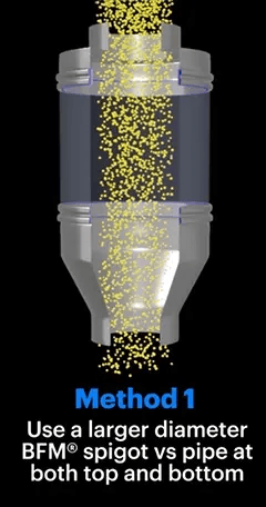
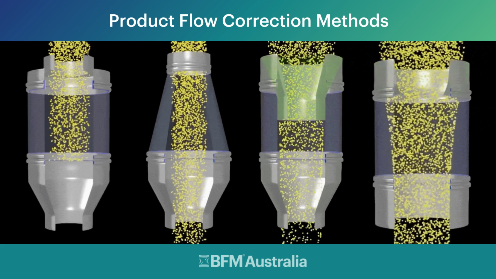
Method 1: Larger Diameter BFM® Spigot vs Pipe |
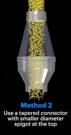
Method 2: Smaller Diameter at Top, Tapering to Larger Diameter at Bottom |
|
This is the simplest option, where you flare out the top pipe and make the diameter of the BFM® spigot at the point of the inlet larger than the pipe feeding the product in. This means you can still use a standard, straight connector, but the product falls through without making contact with the sides. This method is particularly suited to low-velocity/gravity-fed product flows. |
This option utilises our tapered connectors with a smaller diameter at the product inlet, tapering out to a larger diameter at the bottom outlet. This again means the inward flow of the product is narrower than the walls of the body of the connector, so it falls through without making contact with the sides of the connector. This method is also ideally suited to low-velocity/gravity-fed product flows. |
|
|
|
Method 3: Flow Ring Extending Down Inside the Connector |
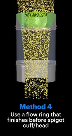
Method 4: Flow Ring Finishes Before Spigot Cuff |
|
Select a spigot diameter the same as your inlet pipe, but add an Insert, or ‘flow correction ring’, inside the spigot that extends down past where the cuff of the connector sits.* This directs the flow of the product into the centre of the spigot to ensure minimal wall contact by the product. This method is suited for both high and low-velocity applications. |
Similar to method 3, however, the flow-correction ring on the inside of the inlet BFM® spigot ends before the cuff of the connector. This again helps direct the powder flow inwards and away from the wall of the connector but is suitable for any diameter spigot and doesn’t impact connector replacement. Ideal for high-velocity flow product. |
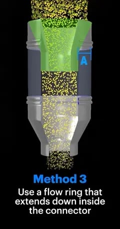
* IMPORTANT NOTE: When using Method 3, you must ensure that the gap between the flow correction ring and the edge of the spigot cuff (dimension 'A' shown below is big enough to allow for connector replacement. We recommend that this is a minimum of 75 mm on each side. |
|
The most effective flow‑correction method depends on your product characteristics, flow rate, cleaning requirements, and overall system design. Each of the four options can help reduce abrasive contact and improve connector longevity — the key is selecting the one that best suits your application.
If you’d like help determining the ideal configuration for your site, contact us to discuss the best solution for your specific application and requirements.